Let’s calculate the size first, The full-color LED module of P5 is 320 * 160mm in size, 15 pieces in length and 12 pieces in height, the led display uses a total of 180pcs led modules.:320*15=4800mm,160*12=1920mm, screen size is 4800mm*1920mm. And then add the side frame, the frame size is 4810 mm * 1930 mm.
P5 indoor module size 320mm*160mm

Make side frame first
Buy 4 * 4 square steel, 4 pieces of 2 * 2 square steel (6m long) from the market.

First, make a 田shape with 4 * 4 square steel, the size of large frame is 4850mm * 1970mm, because the size inside the small frame is the size of the screen. The square steel is 40mm, so it’s this size. It’s better to weld at a 90 degree angle.

After 田shape is completed, start welding small square steel on it. The internal dimension of small square steel is 4810 mm * 1930 mm, and the four corners and the middle part are cut into small sections and welded with the remaining 4 * 4 square steel.
Square steel welding:


2. Install power supply, control card, and led module
After the frame is hung, a gap of 10 mm shall be reserved around it. Because there is no fan in the module, only this 10 mm gap is used for ventilation and heat dissipation.
5V output must be positive and negative. If the power output line is connected reversely, the power line and module will smoke at that time. If the control card is still connected, the card will burn.

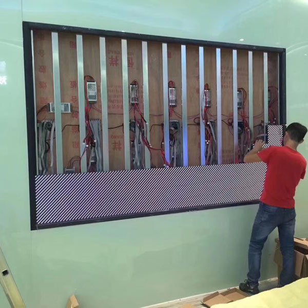
Fix the power supply on the square steel, after the power supply is connected, install the control card, which uses 5 synchronous receiving cards.

3, Connection between receiving card and led module
Each card is equipped with three columns of modules, 36 boards in total so that one card is installed in every three columns. Take 5V from the nearest power supply to power on the card, pay attention to the positive and negative poles, and then connect the five cards with the network cable. The power connector is the input network port, and the input is the Gigabit network card of the computer. Then the output network port is connected to the input port of the second card, and the output port of the second card is connected to the input port of the third card, and so on.

4, Installation led module
From top to bottom or from bottom to top

Five cards are used for the LED screen. One card supports three columns of modules. Each card has 12 T75 interfaces. This screen is also 12 rows from top to bottom,

5. Debug
Power on test after installing one card of three columns of modules, If there is a problem, it should be solved in time, because another group will cover the card and it can’t be tested. There is a test button on the control card, If the installation is normal, the screen will display red, green, blue and white in turn. If the installation is normal, install the next group until the installation is completed.
